
The Jim Kelley 2 Channel Line Amp
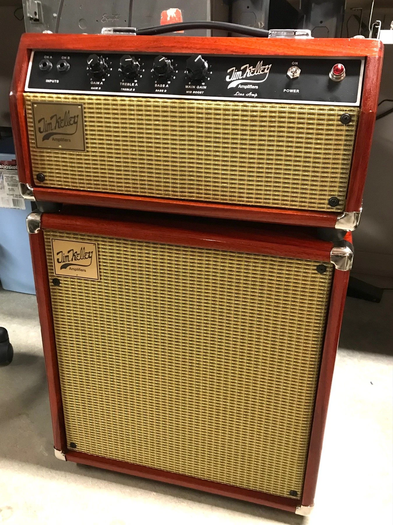
The newly designed amplifier is a two channel Line Amp, with Dual-Concentric controls for Gain, Treble, and Bass. The Main Gain (Master Volume) control for the overdrive B channel has a pull switch for Mid-Boost. The A channel is identical to the original Jim Kelley non-reverb preamp. The amp also has a guitar level, transformer coupled effects loop. The output section is the traditional Jim Kelley matched quartet of 6V6's. The amp has a traditional JK front ends with the Baxandahl style tone network. The back panel of the amp has a stand-by switch, effects loop jacks, speaker jacks, and a gain boost jack. The latter functions as a solo boost by decreasing negative feedback.
The Line Amp has evolved over the years, but the basic concept - the end goal, has remained the same all along. With this amp it has always been my intention to be able to achieve the same harmonic structure in the preamp as one gets by overdriving a quartet of beam power pentodes in a push-pull output section. The obvious advantage of being able to do this is that one would be able to have precise control of the volume without having to sacrifice tone. It has only been within the last 2 or 3 years that I have finally developed the small signal vacuum tube circuit that achieves the results I began looking for 35 years ago. The circuit is a dual-cascode differential amplifier and it produces the harmonics and feel of a well designed tube push-pull power amplifier at preamplifier signal level – or line level. Hence the name, Line Amplifier.
This latest version of the Line Amp is the culmination of 35 years of work toward finding a way to replicate the harmonic spectrum and dynamic characteristics of an overdriven push-pull output section, and produce it at preamp level. I am sincerely delighted to be able to report that I have finally succeeded in designing just such a circuit. I have decided not to build reverb into these amps because of the noise associated with locating the reverb tank in close proximity to the power transformer. In this new amp, since the effects loop is positioned after the overdrive circuitry and Main Gain control, time based effects pedals including reverb and delay are able to produce superior results. I see this as a significant improvement over the traditional design in that it can take advantage of the profound advances made in effects pedal design.
I began building these amps at my home in Arizona in 2018. It has been a rewarding hobby for me. The gratifying part of it is hearing them being played of course, but even more gratifying are the testimonials I receive from those players. Lately I am building just a few amps per year. When I complete an amp I offer it at a private auction which is open to members of my email list. Please send me an email if you would like to be on the list.

Front Panel
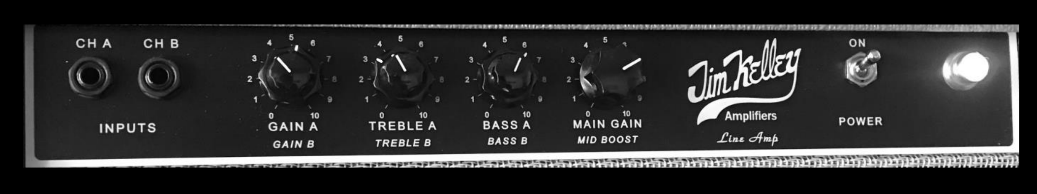
Separate Inputs for each channel; concentric Gain controls for A and B channels; concentric Treble controls for A and B channels; concentric Bass controls for A and B channels; and the Main Gain master volume for the B channel has a pull switch for Mid-Boost. The center frequencies of the Channel B tone knobs have been raised slightly relative to the classic Channel A EQ. The classic amp was voiced to work well clean and for driving output tubes, and the Channel B EQ is optimized for the new overdrive circuit. 3- 12AX7's, 1 - 5751, and of course a matched quartet of 6V6's. 55 Watts true RMS power output into 4 or 8 ohms.
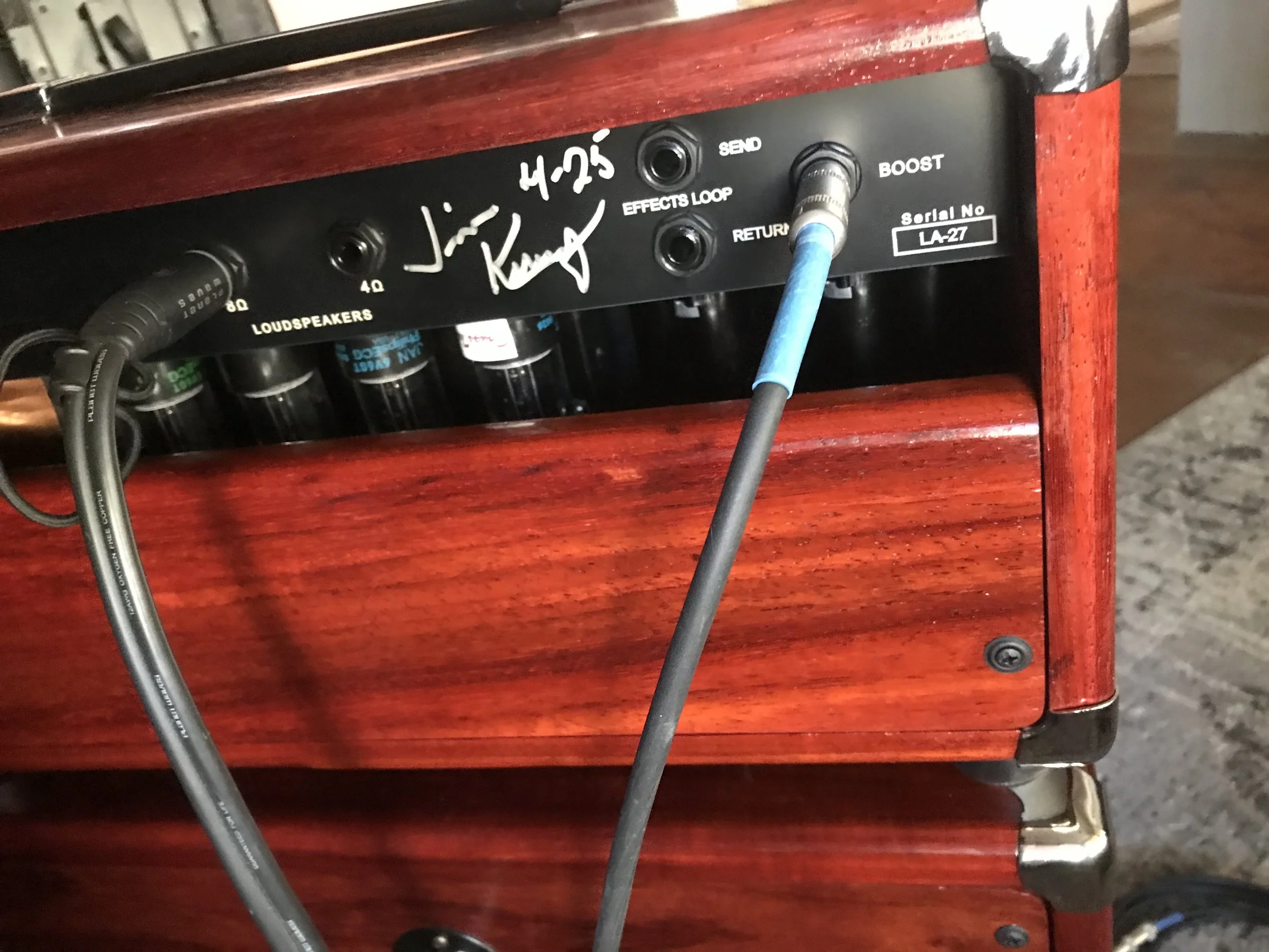
Back Panel
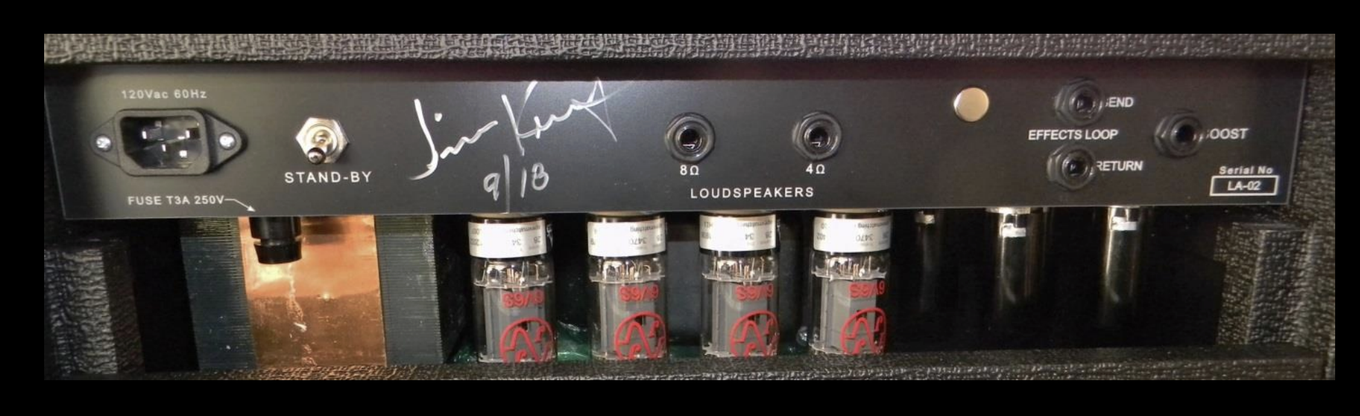
The back panel has, from left to right, a standard IEC power inlet receptacle, wired for one of the following: 100, 120, 230, or 240 VAC depending on customer request. Next is the Stand-By switch. I believe it is important to allow the tubes to warm up before applying high voltage, and it also allows the amp to cool down on breaks without repeatedly thermally cycling the filaments. To the right of that are the 8 Ohm and 4 Ohm speaker jacks, then the serial Effects Loop jacks. All the way to the right is the Gain Boost footswitch jack which provides about a 6 dB signal boost to the output section. Any latching footswitch can control this function. The Effects Loop is positioned in the circuit right after the Main Gain control and is ideal for use with most guitar level effects pedals.
Waveforms, Frequency Sweeps, and FFT Spectra
I have captured waveforms, frequency sweeps, and FFT spectra with the oscilloscope that illustrate time domain and frequency domain performance of the Line Amp.
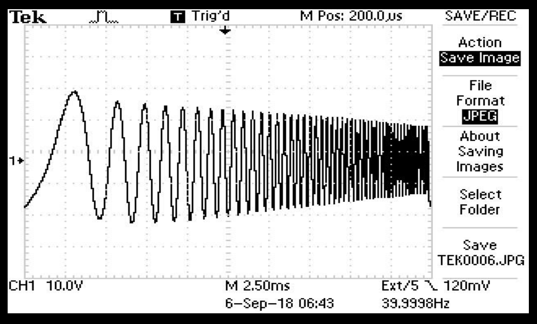
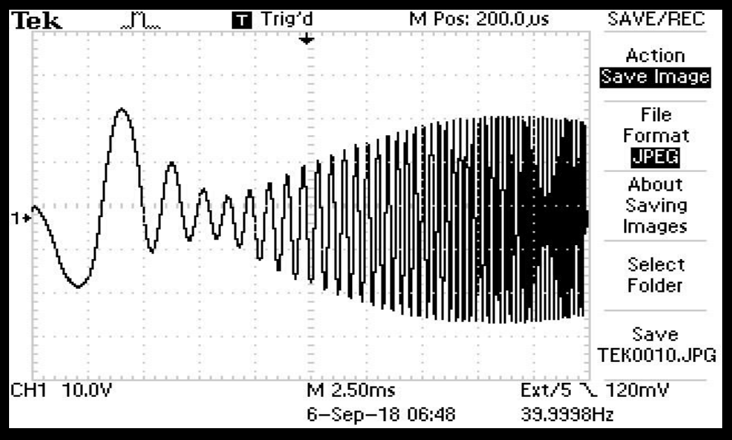
Frequency sweep with Bass and Treble on 5
Showing the effect of the Bright Switch
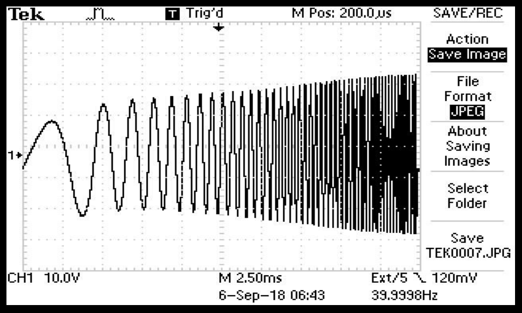
Treble on 5, Bass on 10
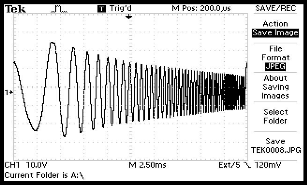
Bass on 5, Treble on 10
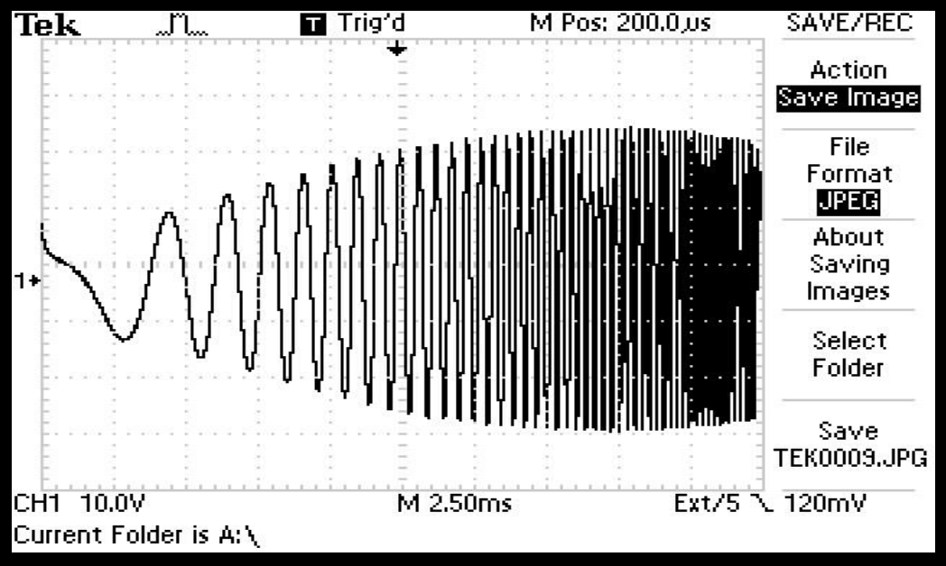
Bass on 10, Treble on 10
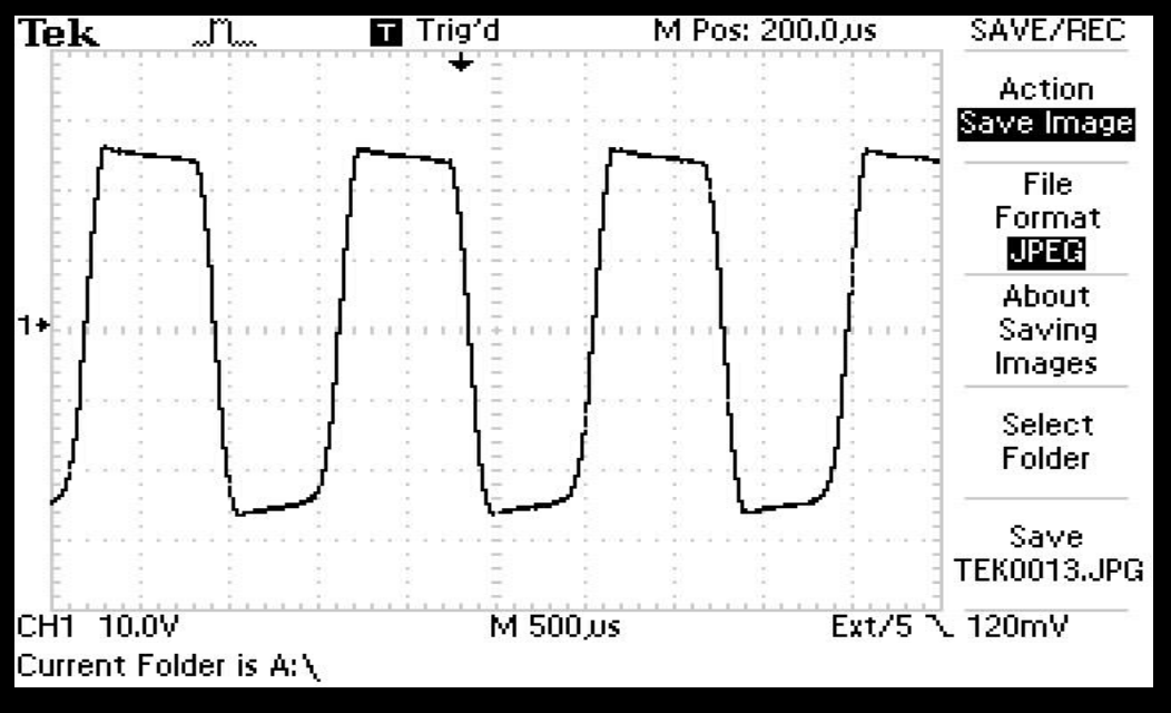
Output section clipping, Main Gain on 10
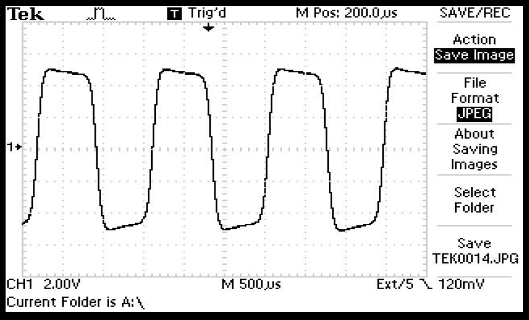
Harmonic Generator clipping, Main Gain on 4
You’ll notice a little bit of a softer leading edge from the Harmonic Generator than from the overdriven output. We must roll off some upper harmonics or the end result will sound overly sibilant when driving the output section into an inductive load. These graphs were made into a resistive load. But you can see they waveforms look very much alike.
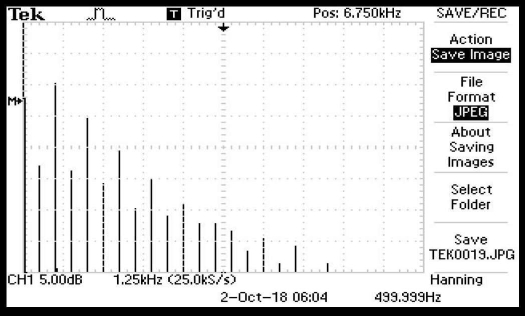
Spectrum of waveform above, Main Gain on 4
The first line on the left is the fundamental, then the 2nd harmonic, 3rd, 4th, 5th, etc. The even order harmonics are subdued relative to the odd order harmonics – just as in the full power spectrum below.
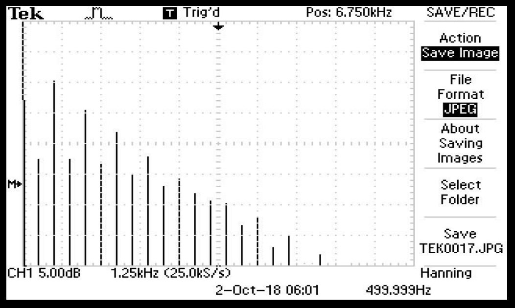
Full Power spectrum, Main Gain on 10
Note the increased height of the fundamental relative to the reference point M due to the increased power level. You can see the higher harmonics (8th and above) are a bit more abundant as we might expect from the waveforms above. Of course the speaker significantly attenuates everything above 5.5KHz or so. The interesting thing to note is how the balance between even order and odd order harmonics is maintained. That was the most difficult thing to achieve.